Groups 1B to 8B The Transition Elements
Overall Relationships of Structures to Activities
These Elements represent the filling of the (3d), (4d) and (5d) orbitals, with 0 to 10 electrons but the filling of the (3p)6 configuration at Argon actually completes the third Period of the Table. The first row of this Transition Block occurs apparently “out of sequence”, after the filling of the (4s)2configuration. This because the (3d) orbitals penetrate the core so poorly, that the (4s) orbital can fill first. Thus, all Transition Elements have “delayed configurations”, [Rare Gas]([n+1]s)2ndm, with n ranging from 3 to 6 and m ranging for 0 to 10, as shown in Table (1).
Table (1) Electronic Configurations of Transition Elements
| 3B | 4B | 5B | 6B | 7B | 8B | 1B | 2B | ||
| Sc | Ti | V | Cr | Mn | Fe | Co | Ni | Cu | Zn |
| (3d)1 | (3d)2 | (3d)3 | (3d)4 | (3d)5 | (3d)6 | (3d)7 | (3d)8 | (3d)9 | (3d)10 |
Spatial and Electronic Structures
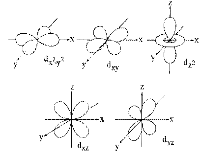
The poor penetration of the core by these (nd) orbitals is caused by the presence of two angular Nodes in their probability distributions, as shown in figure (1). These Nodes force the (nd) electron density to be zero in two directions and only allow the (nd) electrons to penetrate the core in very narrow, solid angle regions. This puts the (nd) orbitals at a strong disadvantage against the ([n+1]2) electrons which are allowed to penetrate from all angles, as shown in Figure (2). However, as the Atomic Number of the elements increase along each Period, each added (nd) electron has no shielding effect against any other (nd) electron, since they are all at the same distance from the nucleus.
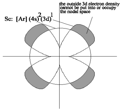
This absence of new shielding means that as positive protons are added to the nucleus along the Period, the (nd) orbitals can become more stable, so that at the end of each Transition Period, the (nd) orbital is more stable than the ([n+1]2) electrons and, as the ([n+1]p) begins to fill to form the next Period in the Main Block, these (nd) orbitals become part of the Core.
Again, as was seen in the Main Block, the addition of layers of ([n+1]d) orbitals increases the atomic radius and should decrease both the Hardness and the Electronegativity of the transition elements down each Group. The actual values of the Hardnesses of these Elements are shown in Table (2) and the corresponding Electronegativities are shown in table (3).
Table (2a) Hardnesses of the Transition Elements
| 3B | 4B | 5B | 6B | 7B | 8B | 1B | 2B | ||
| 310 | 325 | 300 | 295 | 360 | 370 | 350 | 310 | 315 | 360 |
| 290 | 310 | 290 | 305 | 325 | 305 | 305 | 375 | 300 | 470 |
| 245 | 335 | 365 | 345 | 370 | 365 | 360 | 330 | 330 | 525 |
Table (2b) Electronegativities of the Transition Elements
| 3B | 4B | 5B | 6B | 7B | 8B | 1B | 2B | ||
| 325 | 330 | 350 | 360 | 360 | 390 | 410 | 425 | 410 | 425 |
| 320 | 350 | 375 | 380 | 375 | 405 | 415 | 430 | 430 | 400 |
| 295 | 335 | 395 | 425 | 385 | 475 | 515 | 535 | 555 | 480 |
Forms of Transition Elements
The Transition Elements are all metals and most of them are crystalline solids at room temperature. In most cases, these solids have either cubic or hexagonal close-packed Structures. Their characteristic Activities include high melting and boiling points, high mechanical strength and ductility, high conductivity of both heat and electricity and reflective surfaces.
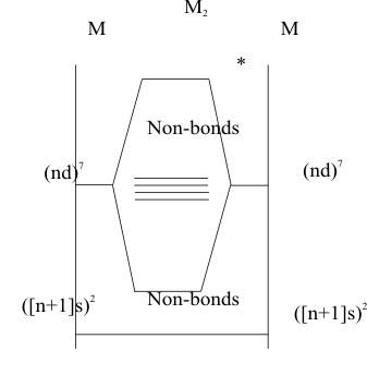
The metallic bonding in these solids is similar in some ways to the bonding in the covalent bonding in the diatomic molecules of the second Period Main Group Elements with the addition of unrestricted, non-bonding (nd) orbitals. As shown in figure (3), the description of a diatomic molecule of an Element of Group 7B is initially the same as that of the diatomic of the corresponding Element in Group 7a, except the σ bond is formed by the overlap of (nd z2) orbitals instead of (p z) orbitals. All of the other (nd) orbitals are defined by symmetry as potential π bonding orbitals. However, like the potentially (pπ) bonding orbitals of the heavy Main Block Elements, when the Pauli and Aufbau Principles are applied, they remain non-bonding because the metal atoms are too large to allow significant (dπ) overlap along the bond axis. Then, like the heavy Main Block Elements, these Transition Block Elements compensate for their inability to form strong (dπ) bonds by forming a (dσ) bonded solid. The difference between the nonmetallic Structures of the Main Block Elements and the metallic Structures of the Transition Block Elements is the difference in local stabilities of the non-bonding (pπ) orbitals in the Main Block and of the non-bonding (dπ) orbitals of the Transition Block. The (pπ) orbitals in the Main Block are very stable and not available to interact with radiant energy. In contrast, the poorly penetrating (dπ) orbitals of the Transition Block have low stabilities and large radii, their resulting weak overlaps form a “band” of weakly bonding and antibonding “Lattice Orbitals”. The available electrons would all be placed into the (dπ) bonding orbitals, localized on the “parental” atoms by the Pauli and Aufbau Principles. However, they are easily dislodged into (dπ) antibonding orbitals, which are delocalized over the whole lattice, by radiant energy. Thus, at room temperatures and above, there is enough energy to “excite” these electrons into the conductive “electron gas” within the lattice, which is the defining characteristic of all metals.
Identifying SONs of Transition Elements
As with the Elements in the other Blocks of the Periodic Table, the Transition Elements are often bound by donor covalent bonds within complicated chemical Structures and their electrical charge cannot be measured experimentally. The consequent theoretical assignment of their SONs generally follows the same Octet Rule used for the other Elements but the similarity of the ([n+1]s) and (nd) orbital energies complicates the procedure.
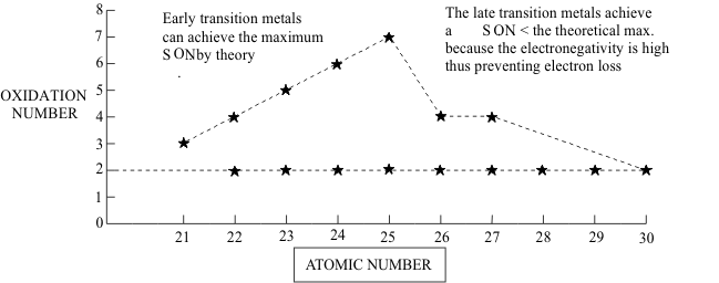
For most Transition Elements, the HOAO is the ([n+1]s) orbital and the removal of its two electrons defines a +II SON. The higher SONs are then generated by successive removal of any available (nd) electrons, as shown in Figure (4). The SONMax, representing the loss of all available (nd) electrons, can be reached in all Transition Element Groups from 3B to 7B. Since this includes all Transition Elements up to the “half-filled” (nd) shell, they are classified together as the “Early Transition Elements”. In contrast, in the “late Transition Elements, from Group 8B to 2B which represent the filling of the (nd) shell, the improving penetration of the core by the (nd) electrons causes a rapid decrease in available SONMax values with increasing Atomic Number.
Between these SON limiting values of + II and SONMax , several intermediate SON values may be possible. In the Early Transition Elements, the poor penetration of the core by the (nd) electrons means that these SONs represent thermodynamically unstable oxidizing agents. These Structures can only be captured chemically if they are made kinetically inert by Pauli pair formation, thus the only SONs of practical importance are found in compounds with all of the (nd) electrons paired into MOs. In contrast,, the improved penetration by the (nd) electrons through the core in the Late Transition Elements means that intermediate SONs are thermodynamically stable and do not require the kinetic inertia provided by Pauli pairing. Indeed, these SONs are so stable that many (nd) configurations of odd-electrons or unpaired even-electrons exist in air-stable compounds, in spite of formally being Free Radicals.
Reduction to Minimum SONs
In reactions of these Elements and those with lower Electronegativities, Pauling’s Electroneutrality Rule predicts that to minimize the total Free Energy of the whole system, these atoms would at least retain or possible gain electrons into their partly filled (nd) orbitals.
This either leaves the Transition Element in a “zero-valent” condition or reduces it to a negative SON in the product of the reaction. Since these reduced species are usually thermodynamically unstable the only SONs of chemical importance are those representing (nd) configurations of Pauli paired bonding orbitals. An example of a zero-valent condition is given by the reaction of metallic Nickel with the gas carbon monoxide to form nickel tetracarbonyl;
Ni + 4CO -> Ni(CO)4 (1)
in which the product is a covalently bonded liquid at room temperature.
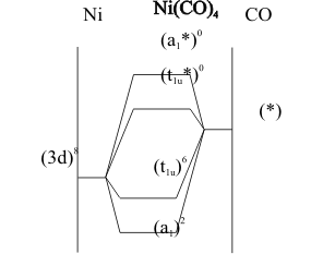
The bonding, shown in Figure (5), is described as “back donation” from the filled, Lewis Base (3d) non-bonding orbitals on a Nickel atom to the empty, Lewis Acid (π*) antibonding orbitals on the carbon end of the carbon monoxide molecules.With cobalt, the analogous anion [Co(CO)4]- forms and is stable enough to support its acid.
Oxidation of the Elements
The Intermediate SONs
The SON of +II, representing loss of the ([n+1] s)2 pair, provides a large proportion of the thermodynamically stable compounds of the Transition Elements. The electronic properties of the First Transition Row (the fourth Period in the Table) ions are shown in Table (3). Compounds of all of these ions are known, except for Sc +II.
Table (3) Electronic Structures Of First Transition Row Elements
| +II Ion | Configuration
(3d)m |
r
nm |
η
kJ/M |
(106)α
(nm3) M/kJ |
χ
kJ/M |
Π
(104)
kJ/M |
| Ca | 0 | 0.10 | 1880 | 0.05 | 3025 | 3.03 |
| Sc | 1 | 0.090 | 575 | 1.27 | 1810 | 2.01 |
| Ti | 2 | 0.086 | 670 | 0.95 | 1980 | 2.35 |
| V | 3 | 0.079 | 710 | 0.69 | 2120 | 2.68 |
| Cr | 4 | 0.074 | 745 | 0.54 | 2240 | 3.03 |
| Mn | 5 | 0.082 | 870 | 0.63 | 2375 | 2.95 |
| Fe | 6 | 0.078 | 700 | 0.68 | 2250 | 2.88 |
| Co | 7 | 0.074 | 790 | 0.51 | 2435 | 3.29 |
| Ni | 8 | 0.073 | 820 | 0.42 | 2570 | 3.67 |
| Cu | 9 | 0.073 | 800 | 0.49 | 2750 | 3.77 |
| Zn | 10 | 0.075 | 1050 | 0.45 | 2780 | 3.71 |
The simplest of these compounds are the “binary salts” in which these cations unite with the common monovalent, divalent or trivalent anions, in stoichiometric formulas; MX 3, MX and M3X2.In these salts, the high Polarizing Power Π of the Lewis Acid cations forces these Lewis Base anions to form donor-covalent bonds. Even so, the lattice Structures are usually consistent with the geometry predicted by Pauling’s radius Ratio Rule.
When these +II ions dissolve, their large radii indicate that they do not hydrolyse like the smaller, more Polarizing Main Block cations, but their Polarizing Power is high enough to attract polar solvent molecules or polar dissolved Lewis Bases as “ligands”, or species which are “tied to” the cation. A wide range of neutral and negatively charged species, including those shown in Table (4) are commonly found as ligands in these complexes. In this Table, the substituents on the donor atoms can be any other atom or group, including the H atom, halogens, or organic groups.
Table (4) Typical Lewis Base Ligands in Transition Element Complexes
| Donor Atom | Neutral Ligands | Anionic Ligands | |||
| Group | Atom | Name | Formula | Name | Formula |
| 5A | N | Amine | R3N | Amide | R2N- |
| P | Phosphine | R3P | Phosphide | R2P- | |
| As | Arsine | R3As | Arsenide | R2As- | |
| 6A | O | Ether | R2O | Oxide | RO- |
| S | Thioether | R2S | Sulfide | RS- | |
| 7A | F | - | - | Fluoride | F- |
| Cl | - | - | Chloride | Cl- | |
| Br | - | - | Bromide | Br- | |
| I | - | - | Iodide | I- | |
In the resulting “complexes” the “coordination number”, cn, defines the number of bound ligands, which can vary from 2 to 12. The value of cn in stable complexes is almost always determined by the Polarizing Power of the cation. For any given value of Π from Table (3), the charge requirement can be satisfied in the two limiting cases of either a small number of highly polarizable ligands or a large number of weakly polarizable ligands. This ligand polarizability is often called its “Donicity”. Thus, the coordination number is predictable from the ratio of these cation and ligand properties ;
cn = Π (M +II) / α (L) (2)
In a minority of cases, this purely electronic prediction can be altered by “steric Interference” in the “coordination Sphere” of directly bound ligands. If some or all of these ligands are large enough to come into direct contact with each other before they get close enough to the metal ion to form a stable bond, some of these “oversized” ligands are rejected from the coordination sphere, reducing the cn from the value predicted electronically down to the value predicted by the Pauling Radius Ratio for these ligands in this complex
Complex Structure and Bonding
Once this combination of electronic and steric factors has determined the cn of a complex, the donor covalent bonding of ligands to Transition Element cations can be described with the LCAO MO model. As usual, the first step is to define the GOs formed from the participating AO's.
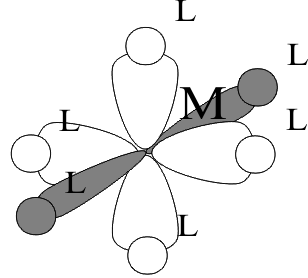
In the simplest case, the AOs of the cations are the cation HOAO, (nd)m and LUAOs, ([n+1]s) and ([n+1]p), while typical Lewis Base ligands use HOAO (np)6 or equivalent HOMOs in “polyatomic ligands” like amines and ethers. To form the corresponding GOs, the full symmetry of the complex must then be determined. The most typical of these is a complex with a cn of 6 in an octahedral Structure, in which the six identical ligands occupy the identical positions at each end of the three Cartesian axes, + ( x, y, z). In this Structure, the (np z) HOAOs of the ligands are directly in line with the (nd x2-y2,z2) and the ([n+1]p xyz) LUMOs of the Transition element cation. This is electronically optimal because it maximizes the GO overlaps and sterically favourable because it minimizes ligand-ligand contact.
To describe the energy of this purely σ bonding condition, the Energy Level Diagram is constructed, as shown in figure (7). Following the model developed by C. J Ballhausen and H. B. Gray in 1964, the most stable MO in the complex is the (a1g) formed by large overlap of the (a1g) GO of the ligands with the ([n+1]s a1g) of the cation. Then comes the MO formed by the smaller overlap of the (t1u) GO of the ligands with the ([n+1]p t1u) LUAO of the cation. Finally, the least stable MO forms from the poorly overlapped ligand (eg) GO and the (nd eg) HOAO of the cation. The remaining ligand GOs, (t1g , t2g , t1u , t2u ), and cation HOAO (nd t2g) have π symmetry and, in most complexes, theses types of ligand and cation orbitals are too far apart in space to have any overlap. Thus, they usually remain non-bonding in these complexes.
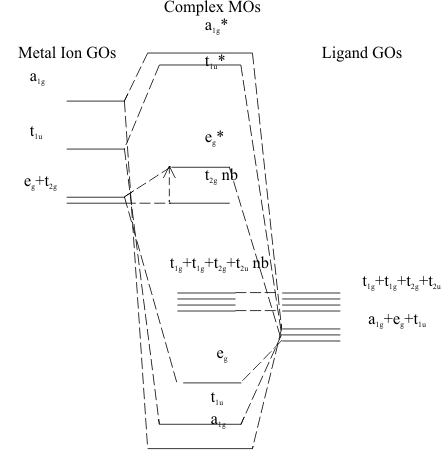
When the Pauli and Aufbau Principles are applied to these Diagrams, the three σ bonding and the four ligand-centred π-non-bonding MOs are fully occupied. Above these HOMOs, the remaining electrons distribute themselves into the cation-centred MOs (ndt2gπnb) and (ndegσ)* MOs. The difference in energy between these two MOs is usually very small and any electrons in the (ndt2gπnb) can be excited into the (ndegσ)* MO with the small amount of energy available in visible light. Since this gives the complex a very obvious bright colour, this energy gap has been studied in all Transition Element complexes for more than 100 years. In the LCAO model it is called the “Ligand Field Splitting Energy” and is identified quantitatively as Δ in figure (7).
In the purely ionic Crystal Field model developed by H. Bethe in 1929, this energy gap was defined as 10Dq. In this model the gap originates from the Coulombic repulsion forces acting on the electrons in the (nd) HOAOs of the cation from anionic, point charge ligands. Since the (ndeg) HOAOs point at the ligands they are destabilized by this repulsion. However, the (ndt2g) HOAOs point between the ligands and Bethe assigned this geometry as a “stabilization” condition. This allowed him to describe the total effect on the (nd) HOAOs as a “barycentric” perturbation, that is, an equally weighted energy splitting of these HOAOs above and below the original HOAO energy, This oversimplified but convenient “Crystal Field” mconcept is shown in Figure (8).
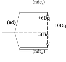
When the Pauli and Aufbau Principles are applied for each of the Transition Element cations, the different possible ways in which the electrons may be distributed can be studied in detail. Since the (ndt2g) HOAOs are all degenerate, up to 6 electrons can be placed at the same energy. If there are between 4 and 6 electrons in this HOMO, some must form Pauli pairs. However, the resulting Pauli spin pairing destabilization energy, which comes from putting two electrons close together in a single orbital “lobe”, can be so strong that it is larger than the 10Dq destabilization energy needed to promote a (ndt2g) electron to the (ndeg) orbital.
If this promotion does not occur, the (ndt2g)m configuration of paired electrons is called a “Low Spin” Structure. However, if promotion of some electrons to a (ndt2g)(m-q)(ndeg)q configuration minimizes the destabilization energy of the whole complex, the resulting electronic Structure is called “High Spin” because it maximizes the number of unpaired electrons in both the (ndt2g) and (ndeg) orbitals. This unpairing formally converts the complex to a many-electron Free Radical form. In complexes of the Early Transition Elements, these High Spin configurations do indeed behave like Main Block Free Radicals because their poorly penetrating (nd) orbitals are large enough to overlap and react with reagent species. However, since the more efficiently penetrating (nd) orbitals of the Late Transition elements have much smaller radii, they do not overlap or react readily with external reagents, but instead retain this Free Radical Structure in many chemical conditions. This thermodynamic stability of High Spin electronic Structures is even more common in complexes of the Lanthanide or Actinide Elements. The unpaired electrons in their highly penetrating (nf)m configurations are almost totally unaffected by the chemical environment of their cations.
To calculate the net stabilization achieved in each of these different electronic configurations, the Ligand Field model, shown in figure (8) was used to define the “Ligand Field Stabilization Energy” LFSE of a ligand field configuration as the sum of all stabilizing electrons at (-4Dq) and destabilizing electrons at (+6Dq) ;
(3)
Then the net stability of the HOMO system of (ndt2g)(m-q) and (ndeg)(q) orbitals becomes ;
(4)
(4)
where (r) is the number of pairs of electrons in the configuration and SPE is the Spin Pairing Energy.
The Maximum SONs
The Rare Gas maximum SONs, representing ([n+1])s)0(nd)0 configurations, can all be reached chemically in the Early Transition Elements, as shown in Figure (8.4). Since they carry no (nd) electrons, both their Structures an Activities closely resemble those of their corresponding Main Block Elements with the same SONs. The only important difference is that the empty (nd) orbitals on the 3B to 7B Transition Elements in these maximum SONs leave the positive nucleus completely unshielded in the (ndπ xy, xz, yz ) directions and therefore provide a new route for Nucleophyllic attack by negatively charged reagents. Thus, the covalently bonded liquid TiCl4closely resembles CCl4 except that it is hydrolysed instantly by the nucleophile water ;
(5)
From this difference it is not surprising that, while maximum SON Main Block Elements accept π electron pairs from Lewis π Base ligands into empty (npπ) orbitals, the corresponding Early Transition Elements accept the same π pairs into their empty (ndπ) orbitals. Thus, the sulfate ion (SO4)2- is pπ ⇒ pπ bonded while the chromate ion, (CrO4)2- is pπ ⇒ dπ bonded. Otherwise, the two anions have identical Structures and very similar Activities in both acid and salt forms.
In contrast, as shown in Figure (4), the Late Transition Elements are too stable to lose all of their (nd) electrons in any chemical reactions. However, since the achievable maximum SONs still have very high Polarizing Powers, Π, they satisfy their high charge requirements in one of two main types of Structure; σ bonded complexes with the largest possible numbers of Hard ligands, giving high cn values, or π bonded complexes with the necessary numbers of Soft ligands, giving small cn values. The σ bonded complexes are typified by the trianion [FeF6]3- and the π bonded complexes by the “Sandwich Compound”dication {[(CH3)5C5]2Fe}2+.
All of these maximum SON compounds of the Late Transition Elements tend to be strong oxidizing agents. As well, if they occur as π bonded anions which avoid hydrolysis in water, they can also form strong Bronstead acids. As with the Early Transition Elements, both Activities depend on the availability of empty (ndπ) orbitals, which can accept electron pairs from nucleophiles. However, in these Late Transition Elements, the (ndπ) orbitals are partly or even completely filled, which severely limits both the π oxidizing and acidic Activities. Thus, Co3+ and Ni4+ are both cations with maximum SONs but neither is an efficient π Lewis Acid because their (ndπt2g)6 configuration completely fills their π acceptor orbitals. As the result, neither cation is an efficient oxidizing agent and neither hydrolyses in water to form an oxyanion with Bronstead acidity.
Indeed, this π shielding of the Co3+ and Ni4+ nuclei by the (ndπt2g)6 configuration is so effective that these cations are essentially kinetically inert. Nucleophyllic Ligand exchange reactions, which happen instantly with the Early Transition Elements, become extremely slow and follow two distinct types of alternative Mechanisms. As defined by C H Langford (from Carleton University) in 1966, two opposite processes are possible at the Rate Determining Step; an Association in which the incoming ligand bonds first to the Transition Metal cation, raising the cn or a Dissociation, in which the outgoing ligand leaves first, reducing the cn. If the two processes occur together, the Mechanism is called an Interchange. In the Association Mechanism, the Free Energy of Activation is high because the incoming ligand must push the π-shield out of position and sterically repel the other ligands into a distorted geometry to bond to the Transition Metal ion. In the Dissociation Mechanism, the Free Energy of Activation is high because the outgoing ligand must break its bond with the Transition Metal ion spontaneously. Clearly, both types of Mechanism are difficult process and their rates often depend strongly on very specific factors in the Structures of complexes and Nucleophiles.