Group 7A; The Halogens (Salt Makers)
Overall Relationships of Structures to Activities
The Elements of Group 7A again begin in the second row of the Periodic Table because the filling of the (1s)2 orbital of Helium completes the first row of the Table. All Group 7A Elements have electronic configurations [Rare Gas ](ns)2(np)5, with n from 0 to 7
Spatial and Electronic Structures
As in Groups 2A to 6A the (ns)2 electrons of Group 7A Elements can penetrate the core of filled p orbitals from all directions but as before, this core provides a shield with no defects which makes this valence pair of electrons unstable. In Fluorine the [(1s)2] core provides such poor shielding, shown in Figure 1a, that both types of valence electrons can penetrate through to the nucleus and there is no significant difference in their penetrating power.
However, in Chlorine and all late Group 7A Elements, the shielding by the filled ([n-1]p)6 core is selectively more effective against (np)5 than (ns)2 electrons because the (np) is forced to penetrate to the nucleus through the maximal shielding of underlying, filled ([n-1]p) lobes of the same shape, Figure 1b.
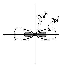
Thus, against the total shielding of the core, Figure 1c, the (np)5 valence electrons are more easily removed than the (ns)2 electrons.
This in energy between valence (ns)2and (np)5 electrons becomes much more pronounced. The net effect of these shielding conditions is that the Effective Nuclear Charge ZEFF, begins at high values in Fluorine and decreases to differentiation by ([core]p)6 by the core becomes stronger down the Group, so that the differences moderate values down the Group. As before this leads to a progressive increase in the atomic radius, and decreases in Hardness and Electronegativity. The correlation of their electronic configurations to their spatial and electronic Structures is shown in Table 1
Table 1 Group 7A Correlation of Electron Configuration to Electronic Structure
| Element
Name |
Structural
Configuration
[core electrons] (valence electrons) |
r
nm |
η
kJ/M |
χ
kJ/M |
| Fluorine | [(1s)2] (2s)2 ( 2p)5 | 0.15 | 680 | 1003 |
| Chlorine | [(1s)2(2s)2(2p)6] (3s)2 (3p)5 | 0.18 | 450 | 800 |
| Bromine | [(1s)2(2s)2(2p)6(3s)2(3p)6] (4s)2 (4p)5 | 0.19 | 400 | 735 |
| Iodine | [(1s)2(2s)2(2p)6(3s)2(3p)6(4s)2(3d)10(4p)6](5s)2(5p)5 | 0.21 | 350 | 650 |
| Astatine | [(1s)2(2s)2(2p)6(3s)2(3p)6(4s)2(3d)10(4p)6(5s)2
(4d)10(5p)6] (6s)2 (6p)5 |
0.22 | - | - |
Molecular Forms of Group 7A Elements
Since the Elements of this Group appear near the end of each Period, their Hardness and Electronegativity reach maximum values. As well, the LCAO model used to describe the Structures of Group 7A molecules, Figure 2, only allows for one purely covalent σ bond.
Thus, the Rare Gas Rule predicts that all of them will occur naturally as diatomic gases, with no solid allotropic forms. When the Aufbau Principle is applied, the least stable electrons are placed in the quadruply degenerate (2p)xy non-bonding orbital. Since these four orbitals all have the same energy, they provide eight equivalent positions for these four pairs of electrons. The remaining σ* antibonding orbital, remains unoccupied, leaving a bond order of one. Thus, in contrast to Groups 5A and 6A Elemental diatomic molecules, this singly bonded Structure is not stable enough to support its own distinct molecular Activities.
Identifying SONs of Halogens
As with the earlier Groups of the p block, these atoms are usually covalently bound within the Structures and their Oxidation Numbers cannot be assigned from experimental measurement of their charges. Their SONs must again be assigned theoretically on the basis of the relative Electronegativities of the atoms in the bond. Following the Octet Rule, the range of Oxidation Numbers in Group 7A is again limited by the Structures of the previous and the next rare gas respectively. Removing all valence electrons to achieve the configuration of the previous Rare Gas gives an upper SON limit of +VII Adding enough electrons to fill the valence shell and achieve the configuration of the next Rare Gas gives a lower SON limit of -I. Following the Pauli Principle, the intermediate SONs occur when Pauli pairs are preserved. Thus, in Group 7A these are the one reduced value of -I, and the oxidized values of +I, +III, +V and +VII.
Electronic Structures of Halogen Compounds
Apart from Fluorine, these Rules assign SON values over the entire range from the lower to upper Rare Gas limits. Thus, all single bonded Group 7A compounds have the molecular formulas; XZ, XZ, X3Z , X5Z or X7Z. However, when the Rules are applied to compounds of Fluorine, they can only identify the value of (SON)F in compounds with Elements with lower Electronegativities. Thus, thee formal SON value of Fluorine in all compounds is limited to -I and 0 so that its typical compounds are limited to those given in Table 2.
Table 2 SON Values for Fluorine in XF Compounds
| Compound | χX | (SON)X | (SON)F |
| LiF | 290 | +I | -I |
| HF | 690 | +I | -I |
| F2 | 1000 | 0 | 0 |
As in the earlier Groups, the type of [ Z-X ] bond, ionic, donor covalent or covalent, depends on the relative polarizing powers Π and polarizabilities α of the two Elements forming the bond pair. Again, the ranges of these parameters make the Group 7A Elements “electronically amphoteric” so that they usually achieve charge satisfaction by covalent sharing rather than by ionic exchange of electron pairs. In spite of this, it is again very useful to identify the Oxidation Numbers of Group 7A Elements in their compounds in order to describe how electron pairs are rearranged during reactions. However, since these atoms are usually covalently bound, their Oxidation Numbers again cannot be experimentally assigned from direct measurement of the their charges. Instead, as in earlier Groups, the SONs must be assigned theoretically on the basis of the relative Electronegativities of the atoms in the bond, using the Rules for Stable Oxidation Numbers.
Reduction to Minimum SONs
In reactions between these Group 7A Elements and less Electronegative metals, Pauling’s Electroneutrality Rule predicts that to minimize the energy of the whole system, the Group 7A atoms would gain electrons into their unfilled (np)5 orbital from the metallic atom. This reduces the Group 7A Element to an anion with a minimum SON of -I and oxidizes the less Electronegative Element to a cation. For example, in reaction with the Alkali Metals, M, the Group 7A Element, Z would be reduced to form a product ;
M + Z ⇒ MZ (1)
in which, depending on its Polarizing Power, the oxidized species M (+N) may bond to the Group 7A anion, to form either ionic compounds such as lithium fluoride, LiF, or covalent compounds such as hydrofluoric acid HF, as shown in Table 2.
In all of these compounds, the assignment of the minimum SON value of -I to the Group 7A Element again defines this Structure as “electron-rich”. As with Group 6A, the Group 7A atom in the Structure of these ZZ’ compounds not only brings enough electrons to make the (Z-Z’) bond pair but also brings three additional lone pairs which remain “non-bonding” in the valence shell. Thus, reactions of these compounds are dominated by donation of one or more of these extra electron pairs, either as a Lewis base or, in the irreversible reaction limit, as a reducing agent.
This “Donicity” increases down Group 7A because increasing shielding by the core makes the filled (ns)2(np)6valence shells increasingly unstable. However, the decrease in χ is extremely large from F to Cl, while from Cl to Br, it is very small. This difference occurs because the 4p valence electrons of Br are only shielded from the ten protons corresponding to filling the (3d)10 shell by the 30% of d electrons in the dz2 and dx2-y2 dσ lobes which occupy the same region of space as the 4p orbitals, as shown in Figure 3a..
The shielding of 4p by the 70% of these electrons in the filled dxz,yzxy dπ lobes is insignificant, as shown in Figure 3b..
Therefore the 4p electrons are exposed to a Coulomb attraction force equivalent to 7 extra protons. Thus the decrease in the χ of Br from Cl is minimal. Then, in the step from Br to I, the addition of the second shield of (4d)10 makes a more effective d-orbital shield because two layers of filled dσ orbitals can provide an effective shield against the 5p orbitals and the drop in χ is large. However, the shielding is never large enough for this Group to achieve the change from a nonmetal to a metallic Element seen in the previous Groups.
The “Halogenide” Compounds
All of the Group 7A Elements form ZH compounds, which are identified by the suffix “ide”, connoting ionic bond character. Their Structure and Activity properties are given in Table 3. As expected, the changes in Structures and Activities of these compounds again follow the changes in Hardness and Electronegativities of the Elements down the Group.
Table 3 The Structures and Activities of ZH Compounds
| Name | Formula | Bond
Stability SB
(kJ/M) |
Bond Type
TB
(Δ kJ/M) |
Acidity
pKA(25C) |
| Hydrogen
Fluoride |
HF | 565 | 313 | 3.45 |
| Hydrogen Chloride | HCl | 482 | 110 | -7 |
| Hydrogen
Bromide |
HBr | 362 | 45 | -9 |
| Hydrogen
Iodide |
HI | 295 | -40 | -11 |
Bond stabilities, SB again decrease but bond types, TB, defined as the difference in Electronegativity between the Element and Hydrogen, only reverse from (H+-Z-) in HBr to (H–Z+) in HI. There is no Bronstead Basicity of these compounds but all are Bronstead acids which increase in strength down the Group, following the decreasing (H-Z) bond strength rather than the decreasing Polarizing Power of the Z- anion
Again, because of their importance, the Structure and Activity properties of these molecules have been described by both Valence Bond and the Molecular Orbital models. The Valence State Electron Pair Repulsion theory describes all of these molecules with one pair bond and three lone pairs with hybridization still defined as sp3. As before, if these pairs repel each other equally, this molecule should still be tetrahedral, with an “inter-pair” angle of 109.9o. In diatomic hydrohalides this question is irrelevant and the simple LCAO MO provides a description similar to that for the Z2 molecules, Figure 2, in which the lone pairs reside as non-bonding pairs in the (ns) and (np)xy orbitals. However, the Lewis Basicity or Polarizability of the halide ions, Z-, increases down the Group and they can form donor covalent bonds either by donating one pair as a “ligand” or two pairs as a “bridge” to a wide range of Lewis acids.
Oxidation to Maximum SONs
In the reactions of Group 7A Elements with more Electronegative nonmetals, Pauling’s Electroneutrality Rule predicts that the Group 7A atoms would lose electrons from either or both of the (ns)2 and (np)5 orbitals to the nonmetallic Element. From the Pauli Principle, this oxidizes the Group 7A Element to stable cations of Oxidation Numbers +I, +III +V or +VII, with the Structural parameter values given in Tables 3 to 6, and reduces the nonmetallic Element to an anion.
Table 3 Electronic Structures of Stable Group 7A Oxidation Number +I
| Stable
ON |
Configuration
[Core](valence) |
r
nm |
η
kJ/M |
(106)α
(nm3)M/kJ |
χ
kJ/M |
Π (10-4)
kJ/Mnm |
| F +I | [ He ](2s)2(2p)4 | - | - | → | - | - |
| Cl +I | [ Ne ](3s)2(3p)4 | 0.095 | 520 | 1.65 | 1775 | 1.87 |
| Br +I | [ Ar ](4s)2(4p)4 | 0.105 | 475 | 2.45 | 1625 | 1.55 |
| I +I | [ Kr ](5s)2(5p)4 | 0.12 | 420 | 4.1 | 1425 | 1.18 |
| As +I | [ Xe ](6s)2(6p)4 | - | - | → | - | - |
Table 4 Electronic Structures of Stable Group 7A Oxidation Number +III
| Stable
ON |
Configuration
[Core](valence) |
r
nm |
η
kJ/M |
(106)α
(nm3)M/kJ |
χ
kJ/M |
Π (10-4)
kJ/Mnm |
| F +III | [ He ](2s)2(2p)2 | - | - | → | - | - |
| Cl +III | [ Ne ](3s)2(3p)2 | 0.095 | 675 | 1.27 | 4500 | 4.74 |
| Br +III | [ Ar ](4s)2(4p)2 | 0.105 | 550 | 2.1 | 4025 | 3.83 |
| I +III | [ Kr ](5s)2(5p)2 | 0.115 | 150 | 10.15 | 3325 | 2.89 |
| As +III | [ Xe ](6s)2(6p)2 | - | - | → | - | - |
Table 5 Electronic Structures of Stable Group 7A Oxidation Number +V
| Stable
ON |
Configuration
[Core](valence) |
r
nm |
η
kJ/M |
(106)α
(nm3)M/kJ |
χ
kJ/M |
Π (10-4)
kJ/Mnm |
| F +V | [ He ](2s)2(2p)0 | - | - | → | - | - |
| Cl +V | [ Ne ](3s)2(3p)0 | 0.03 | 1600 | 0.002 | 7950 | 26.5 |
| Br +V | [ Ar ](4s)2(4p)0 | 0.04 | 1400 | 0.005 | 7150 | 17.9 |
| I +V | [ Kr ](5s)2(5p)0 | 0.1 | 725 | 1.4 | 6500 | 6.5 |
| As +V | [ Xe ](6s)2(6p)0 | - | - | → | - | - |
Table 6 Electronic Structures of Stable Group 7A Oxidation Number +VII
| Stable
ON |
Configuration
[Core](valence) |
r
nm |
η
kJ/M |
(106)α
(nm3)M/kJ |
χ
kJ/M |
Π (10-4)
kJ/Mnm |
| F +VII | [ He ](2s)0(2p)0 | - | - | → | - | - |
| Cl +VII | [ Ne ](3s)0(3p)0 | 0.025 | 11300 | 0.0001 | 22300 | 89.2 |
| Br +VII | [ Ar ](4s)0(4p)0 | 0.04 | 4350 | 0.0015 | 14225 | 35.6 |
| I +VII | [ Kr ](5s)0(5p)0 | 0.1 | 700 | 1.43 | 12500 | 12.5 |
| As +VII | [ Xe ](6s)0(6p)0 | - | - | → | - | - |
The strength and type of bonding which then occurs between the oxidized and reduced species depends on the balance of their Hardness and Electronegativity values and can be estimated again with an LCAO MO analysis
Halogen Halides; the “Interhalogens”
As with the Group 6A Elements, the simplest oxidation reactions occur when the nonmetallic Element acquires the valence electrons of the Group 7A atom, becoming reduced to a stable anion, while the Group 7A atom is oxidized to a cation. In oxidation reactions of Halogens with Halogens, either homogenous or mixed “interhalogen” covalent molecules are formed such as;
Z2 + 7 Z’2 ⇒ 2 ZZ’7 (2)
In general, these compounds have formulas ZX2, ZX4 or ZX6 corresponding to their SONs, as shown for the halofluorides in Table 7. All of the possible compounds are known with the exception of those in brackets.
Table 7 The Halofluorides
| Cation | +I | +III | +V | +VII |
| Cl | ClF | ClF3 | ClF5 | (ClF7 ) |
| Br | BrF | BrF3 | BrF5 | (BrF7 ) |
| I | IF | IF3 | IF5 | IF7 |
The, empty, electron deficient (np)z lobes on the Z +I cations overlap with the filled (2p)z valence lobe of F- to form a donor covalent bond. However, the higher shielding in the heavier congeners progressively reduces this Lewis acidity and weakens this bond, going from ClF to IF.
In the Z +III cations, the removal of a pair of electrons from the valence orbital raises the formal charge on the cation. However, this oxidation does not change the underlying shielding by the filled core orbitals. Thus, for each Element, the effective charge increases only slightly and must now support three weaker bonds instead of one strong bond. As in the ZZ’ compounds, these bonds again become progressively weaker down the Group.
In forming the bonds in these ZZ’3 compounds, one of the two non-bonding pairs in the valence shell of the cation can occupy the (ns) orbital but the other must occupy an (np) lobe. However, to satisfy the formal charge, the same (np) orbital must also accept three more pairs. To describe the expanded valence Structure of these molecules, the LCAO MO can be set up at first in the highest possible symmetry. For these molecules, this is done by assuming that all three Z atoms are chemically equivalent, so that the highest symmetry is a flat triangle. This gives a set of GOs for the Z3 and Z’ atoms which are identical to those derived for H3 and N respectively in NH3 and the LCAO MO energy level diagram is set up using the three degenerate (np) valence orbitals of Z and the three degenerate (npσ) orbitals of the three Z atoms. The resulting MO energies are given in Figure 4a..
However, applying the Aufbau and Pauli Principles, the least stable pair of valence electrons is forced to enter the (e*) antibonding MO in a diradical Structure. However, the Jahn-Teller Theorem then says that this antibonding energy can be minimized by allowing this degenerate MO to split into two new MOs One will be more stable while the other will be equally less stable than the original (e*). However, this splitting Activity causes a distortion in the Structure of the molecule, which forces the Z atoms into chemically non-equivalent positions. This reduced symmetry is used to identify the MOs of the real molecule, as shown in Figure 4b.
. In this stabilized but distorted Structure, the Aufbau and Pauli Principles show that the least stable valence pair is now accommodated in an MO stabilized enough to be non-bonding orbital while its highly antibonding partner from the original (e*) remains empty. The same distortion process occurs in the Z5Z’ and Z7Z’ interhalogens for the same reason.
Hydrated Oxides of Halogens
The hydroxyl derivatives of Group 7A Elements would again spontaneously release a Hydrogen ion by an SN1 Mechanism. As in earlier Groups, this ion would then react with the (O-H) group beside it in the Structure to form a molecule of H2O which is ejected from the Transition State. Again, this leaves behind a dehydrated product with a new (Z=O) double bond, as shown in Figure 5.
However, as with the Group 5A Elements, the fact that the SONs are all odd numbers means that fully dehydrated oxides must be free radicals, formed by combinations of dehydration and disproportionation reactions as shown in Figure 5. As expected, these free radicals then tend to stabilize by dimerization reactions to pair up their unpaired electrons. Strange geometries then arise as the antibonding electron pairs are accommodated in these electron-rich oxides.
Redox Activities of Halogens
The range of SONs available for Group 7A Elements, as shown in Figure (11.5), means that each Element below Fluorine in the Group spans the full range of Reduction-Oxidation Activities. As in the previous Groups, these highly oxidized forms of each of the heavier Elements are increasingly endergonic and only exist because of their kinetic inertness. This is entirely due to the formation of strong donor covalent double bonds from the oxide anions to the very small oxidized halogen cations, as shown in Tables (11.4) to (11.6). In fact most of these compounds are so endergonic that they are detonators which can explode violently from a slight mechanical shock or mild heating. The worst of these is Cl2O7 , closely followed by perchloric acid (HO)ClO4. Down the Group, the increase in shielding of the valence (np) AOs by the core again increases the Spontaneity of Reduction by ZH hydrides, while decreasing the Spontaneity of Oxidation by both the oxidizing acids (HO)ZON and their dimerized oxides. All of these Activities have been characterized with the compounds of Chlorine, Bromine and Iodine. Typical unbalanced reactions of halogen compounds as reagents and the necessary reaction conditions are shown in Table 8.
Table 8 Typical Redox Activities of Group 7A Elements
| Species | SONY | Reducing Agent | Oxidizing Agent | Spontaneity | Lability |
| ZH | -I | 2ZH + OH
- →
Z2 + H2O + 2e- |
- | High | Inert |
| Z(OH) | +I | Z(OH) + OH
- →
ZO3- + 2H2O + 4e- |
ZO-
+H2O + 2e- →
ZH + 2OH - |
Low | Labile |
| OZ(OH) | +III | - | - | (a) | - |
| O2Z(OH) | +V | - | ZO3- +
6H+ + 5e- →
½ Z2 +3H2O |
Low | Labile |
| O3Z(OH) | +VII | - | ZO4- +
2H+ + 2e- →
ZO3- + H2O |
High | Inert |
(a) The “halous” acids are very unstable and these reactions have not been measured.
Redox Reaction Mechanisms
As in Group 6A, the complicated changes in Structure that occur during these redox reactions with Group 7A atoms are so complicated that they cannot occur in one step but proceed instead as multistep Redox Mechanisms.
Both the Br- and I- anions can be used as practical reducing agents. The I- anion in particular is routinely used in redox analytical titrations of easily reducible analytes. Typical of these “iodometric” procedures is the redox titration of hydrogen peroxide ;
H2O2 + 3I- + 2H + ⇒ 2H2O + I3- (3)
in which H2O2 receives two electrons from two of the three I- anions which fill the antibonding (σ*) MO of H2O2 and lower its Bond Order to zero. This splits the reduced molecule into two hydroxide ions which are converted into two water molecules in the acidic solution. The two iodine atoms combine to form an I2 molecule which forms a water-soluble triatomic complex with the remaining iodide anion. Clearly, any one of these steps could be the rate-determining process.
The oxidized forms of the halogens are equally useful as oxidizing agents. The hypohalous anions ZO- are all mild oxidizing agents and ClO- is well known as “Javex” bleach. The more highly oxidized forms are often used in controlled oxidations in synthesizing specific organic compounds.
One example is the oxidation of phenols to quinones by periodic acid ;
Acid-Base Activities of Halogens
The range of SONs available for Group 7A Elements, as shown in Figure (11.5), also means that each Element after Fluorine spans the full range of Acid-Base Activities. However, the usual increase in shielding of the valence (np) AOs by the core down this Group decreases the Acidity of the hydrated oxides HOZO5. All of these Bronstead acid reactions are shown Table 9, with Acid constants where available or estimated by a cubic interpolation suggested by Pauling.
Table 9 Group 7A Acid Strengths
| Species | SONY | nO | Acid Reaction | pKA (Z=) |
| ZH | -I | 0 | ZH + H2O ⇌
H3O+ + HZ |
F
3.45
Cl -7 Br -9 I -11 |
| HOZ | +I | 0 | HOZ + H2O
⇌
H3O+ + ZO- |
Cl 7.53
Br 8.63 I 10.64 |
| (HO)ZO | +III | 1 | (HO)ZO + H2O
⇌
H3O+ + ZO2-- |
Cl 1.95
Br 3 I 4 |
| (HO)ZO2 | +V | 2 | (HO)ZO2 +
H2O ⇌
H3O+ + ZO3-- |
Cl -1.2
Br 1 I 0.77 |
| (HO)ZO3 | +VII | 3 | (HO)ZO3 +
H2O ⇌
H3O+ + ZO4-- |
Cl -10
Br -1 I 1.64 |
These trends in pKA values again reveal the influence of shielding on the Structures and Activities in a Group of Elements. For each Element with SON -I, the Hydrohalc acids are strong. However, oxidation to SON +I results in a much weaker Hypohalous acid and acid strength only increases slowly with increasing SON. Within SON -I, the pKA values of the ZH acids again fall smoothly, showing that the acids get stronger going down this Group from Chlorine to Iodine. However, the strengths of the acids with intermediate SONs, again oscillate, while the trend in strengths is again reversed in the fully oxidized acids. As in Group 6A, this reversal in Group acidity Activity follows the change in the form of the Structural shielding in the valence orbitals with increasing SON. In the reduced species the shielding becomes less efficient down the Group because the core consists of one, then two (nd)10 shells which shield poorly against the filled ([n+1]p) valence orbital.
Thus, the valence electrons, including the (Z-H) bond pairs are pulled progressively into the cores of the heavier atoms, decreasing the (Z-H) bond strength and increasing acid strength. Conversely, in the oxidized species, the O2- bond pairs are donated directly into all of the empty ([n+1]s,p) valence orbitals, forming the (ns,pσ) and(npπ) bonds of the (Z=O) Structure. The (npπ) bonds form strongly with Cl +VII at the expense of the strength of the (O-H) σ bonds, making (HO)2SO2 a strong acid. However, in the Br +VII and I +VII acids, the shape of the one then two (nd)10 shells in the core causes them to shield very strongly against these (npπ) donor bonds. This pattern of Activity therefore confirms the conclusions from the Group VI acids that the π bond pairs are pushed back onto the O atoms and strengthen the (O-H) bonds progressively down the Group, reducing the acidities of these species.
Solid State Structures
All of these acids react with Bronstead bases to produce salts .which precipitate as crystalline solids when the solvent is removed,. In these solids, the highest thermodynamic stability is achieved when the cations from these bases are places as near as possible to the greatest number of the acid anions. In all salts, this “closest packing” Structure is constructed alternating planes of cations and anions. However, this layering can occur in two basically different ways, leading to several types of closest packing systems. The minimal sets of layered cations and anions needed to show the differences between these two Structural systems are shown in Figures 6,a,b.
Both layering systems start with a plane of one type of ion, called layer A. The second plane, called layer B is formed by placing the complementary ions in half of the depressions left between the ions of layer A. To form the third plane, a layer of the first type of ions must is added on top of layer B. However, this third layer can be placed onto layer B in two completely different types of position, creating two different layerings. In one of these Structures, Figure 6a, the third layer is placed in that half of the depressions between the ions in layer B which are directly above the ions of layer A. This is called the ABA layering, Figure 6b. In the alternative Structure, Figure 6c, the third layer is placed in the other half of the depressions of layer B which are directly above the unoccupied depressions in layer A, forming the ABC layering shown in figure 6d.
Looking at the top of each Structure, the ions in each layer form rings of six ions as nearest neighbours for any single ion. For this reason, the “lattice” of ions is described as “hexagonal close packing” However, looking at the same Structures atoms from the corners, these 3D structures can be described in three categories of “cubic close packing” called Primitive Cubic, Body-Centred Cubic and Face-Centred Cubic, as illustrated in Figures 7,a,b,c.
In each of these cubic cells, each of the ions can be classified by its number of nearest neighbours in three dimensions. In the Primitive cell, each corner ion has neighbours on +x, +y and +z directions. This gives it a total of six nearest neighbours, so the ionic Structure is described as “six coordinate”. In the Body-Centred cell, the ion at the three-dimensional centre of the cell shows that all ions have eight nearest neighbours and are called “eight coordinate”. Similarly, the ion in the centre of each face in the Face-Centred cell is “twelve-coordinate”.
Lattice Energies of Solid State Salts
The stability of the solid state form of all salts can be described by the Coulombic force of attraction between the positively charged cations and the negatively charged anions. This electrostatic force binds the “lattice” of these ions together in their regular, crystalline Structures. The thermodynamic stability of this lattice can be determined either theoretically or experimentally. Theoretically, the Coulombic attraction of Avogadro's number, N of opposite electrical charges, Z+ on the cations and Z- on the anions, at long range distance r, is given by EC, and is counteracted by the Coulombic repulsion ER of their nuclei at short range. At the distance where these opposing forces balance, the structure of the lattice reaches its greatest stability and is defined as the Lattice Energy, U, of the solid salt ;
Experimentally, this Lattice Energy cannot be measured directly but it can be defined by a "cycle" of thermodynamic energy measurements, called the "Born-Haber cycle", shown in Figure 8.
Figure 8 The Born Haber-Cycle for the Solid Salt MX
In this cycle, the contributions to the Lattice energy, U, are broken up into a set of heats of reactions which can be measured. Endothermic processes are indicated by (+) and exothermic by (-) signs. Thus, for the metal, going from the Standard State of the element as a solid at room temperature, the heat needed to make it into a gas is ΔHAM(+), then to extract an electron is ΔHIE (+). Similarly, for the nonmetal, the energy needed to go from the Standard State as a diatomic gas at room temperature to a gas of atoms is ΔHAX (+) and then to acquire an electron is ΔHEA(-). The heat released when one Mole of these gaseous metal cations react with one Mole of the gaseous non-metal anions is then defined as the experimental Lattice Energy, U (-);
![]() (6)
(6)
where ΔHf(+) is the Standard Heat of Formation required or released during formation of the salt from the Standard States of its elements.
The Lattice Energy U(-) of NaCl calculated with equation (5) is 788 kJ/ M, meaning that 788 kJ of energy is needed to break all the bonds in 1 Mole of solid NaCl, to produce 1 Mole of Na+ ions and 1 Mole of Cl- ions.
The Radius Ratio Structural Rule
The type of cubic cell adopted by a particular salt depends on the difference in radius between the cations and the anion. If they have the same radius, there is enough space around the cation for six anionic nearest neighbours and the salt adopts the Primitive cell, giving the cation its six nearest neighbours in an octahedron. However, if the cation is bigger than the anion, there is enough space for eight nearest neighbours and the Structure reorganizes to the Face-Centred cubic cell, giving the cation its eight nearest neighbours in a cube. Conversely if the cation is smaller than the anion the repulsion between anions, shown in the second term of equation (5), reduces the space available to anions. The Structure can then reorganize in one of two ways. It can adopt the Face-Centred cell, giving the cation its four nearest neighbours in the square plane, or it can adopt a distorted form of the Body-Centred cell in which alternate corners are unoccupied, giving the cation four its nearest neighbours in the remaining tetrahedron.
These trends were summarized by Pauling as a Radius Ratio Rule. This Rule correlates the “Structural” properties of the salt represented by the ratio of their cationic and anionic radii, [r+/ r-]to the “Activity” of the salt in adopting the most stable geometry. The Rule shows that each geometry gives the best stability for a certain range of the Ratio. Then at critical values of the Ratio, the geometry switches to the next form allowing the cation to have fewer or more nearest neighbours, as indicated in Table 10.
Table 10 Critical Ratios for Crystal Structures.
| Coordination Number n | Critical Ratio [r+/ r-] | Stable Geometry |
| 2 | ⇕ | Linear |
| 0.155 | ||
| 3 | ⇕ | Trigonal |
| 0.225 | ||
| 4 | ⇕ | Tetrahedral |
| 0.414 | ||
| 6 | ⇕ | Octahedral |
| 0.732 | ||
| 8 | ⇕ | Cubic |
| 1.00 | ||
| 12 | ⇕ | Dodecahedral |
Description of Unit Cell Structure with “Symmetry Elements”
In each of these unit cells, all of the atoms found in corners or likewise all those found in body centres or face centres are chemically equivalent. For this reason, all of these cells are described as bodies possessing “High Symmetries”. To quantitate this idea, these bodies are described by all of the ways in which they can be moved to new positions where the look identical to their original Structures. The special ways of moving the body which do achieve this identity are called “Symmetry Operations” for the body. There are three basic types of Symmetry Operations’ shown in Figures 9 a, b, c, which take place with respect to their corresponding “Symmetry Elements”. These Symmetry Elements are catalogued by a system of priorities, Axes are most important and are ranked by their order n. Planes are next in importance and are ranked by their complexity from the most complex “horizontal” reflection of top to bottom, through the “diagonal” reflection through corners to the simplest “vertical” reflection through edges. Inversion is lowest ranked and can only take place through the “origin” of the body.
a. Rotation through an angle 2π/n about a (Cn) Axis of Symmetry.
Figure 9 a, b, c The Three “Symmetry Operations” acting at their “Symmetry Elements”
In the cubic unit cells of solid lattices, the highest ranked Elements are the C4 Axes which carry the 90o rotations of the square sides around the x or y or z axes.. The next are the C3 Axes which carry the 120o rotations of the diagonal corners around the body diagonal. The last are the C 2 axes which carry the rotation of any edge around the xz or yx or xy plane diagonals. The next highest ranked Elements are the Horizontal, then the Diagonal and finally the Vertical Planes which allow reflection of one half of the cube onto its opposite half. Finally the cube does contain in Inversion Origin which allows the cube to be “turned inside-out”. In all, the Primitive Cube has 48 Elements of Symmetry and, apart from a sphere, is the “Highest Symmetry Object” known in three-dimensional geometry.
If all of these Elements are taken together, they define the “Total Symmetry” of the unit cell. Since all of these Symmetry Elements pass through a unique point in space called the origin, this total symmetry is defined as the “Point Group”of the cell. There are 32 different possible Point Groups. This description is a very useful shorthand for uniquely defining all chemical Structures. Stating the full symmetry of a compound leaves no doubt about its shape and provides the language needed to define the ways in which the bonds are distributed inside its Structure. The Woodward-Hoffman Rules are actually correlations based on forming electron distributions with identical symmetries. The terms σ and π, which are used to discriminate types of bonds, and the labels used to identify all MOs are derived from the symmetry of each molecule.
Densities of Unit Cells of Crystalline Solids
The Point Group of the cell defines the total number of atoms, n, of each chemical type which occupy the cell. Using this knowledge together with the atomic weights AW of the cations and anions and the size of the unit cell, a, makes it possible to predict the density of the solid ;
The number of atoms of each chemical type, n, identified in the cell the Point Group symmetry can be calculated by multiplying the number of these atoms participating in the cell by their specific partial occupancies within the cell. Thus, there are eight atoms at chemically equivalent corner positions in all cells. However, each of these atoms is a participant in the seven other cells which share that corner. Thus the participation in each cell is only 1/8. When this calculation is done for all types of chemically equivalent atoms in all three cell types the net numbers are defined in Table 11.
Table 11 Cubic Unit Cell Occupancies
| Atoms at ; | Primitive | Face-Centred | Body-Centred |
| Corners | 1 x (1/8) | 1 x (1/8) | 1 x (1/8) |
| Body | 0 | 1 x 1 | 0 |
| Face | 0 | 0 | 6 x (½) |
| Total | 1 | 2 | 4 |
The AWs are defined by the identities of the cations and anions and the length of the cell side, a, can be determined theoretically or experimentally. Theoretically, if the assumption is made that, because of their like negative charge, all of the anions are just “touching” each other, then the distance a is the sum of the radii of the anions in the corner positions. Experimentally, the length of the unit cell is determined from X-ray crystallography.
Determination of Solid Structures
X-rays are simply focussed beams of light with very short wave lengths. Their short wave lengths are chosen to match the usual distances between atoms in the solid state so that they will reflect or “Diffract” from planes of these atoms with constructive interference. This means that the X-ray which reflects from one plane will either reinforce or cancel the X-ray reflecting off the plane of atoms one layer below, depending on the initial angle of incidence. They can only reinforce if they reflect in-phase and this requires that the ray coming from the lower layer must be one or more full wave lengths delayed before ti recombines with the ray reflected from the top layer. This condition was discovered by the father and son team of William and Lawrence Bragg in 1912. The “Bragg Diffraction Law”, of this constructive interference shown in Figure 10 ;
is;
which can be rearranged to solve for the interplane distance, d, as ;
If the X-rays are reflected off the top surface and the underlying layers of the Primitive cell, the interplane distance d is identical to the cell size a. However, if the solid is tipped at some other angle to the X-ray, the beam would reflect from other layers of the lattice and d would not be the same as a . Then, a three-dimensional geometric “analysis” must be done to calculate the unit cell distance, a from the interplane distance d observed for that particular angle. For complicated lattices containing large molecules, this analysis remains well defined but becomes very tedious. Thus, in most modern X-ray systems, this analysis task is fully computerized. This makes it possible to detect the Structures of almost any crystalline material and in some cases, to obtain useful information about the less organized Structures of liquids, glasses or gels.
While this power has been extremely useful in defining QSARs for inorganic and organic compounds, it had its first major impact on society at large with the discovery of the double helix Structure of DNA by James Watson and Francis Crick in 1953. Since then, the Structures of many other “nucleotides”, proteins, lipids and bone tissue have revolutionized biochemistry, biology and medicine. Now, since the Structures of many of the catalytic proteins called enzymes have been determined, it has become possible to deliberately design and synthesize therapeutic drugs which fit exactly into the active sites of enzymes. In a process called “competitive inhibition” of the enzyme, these drugs prevent the entrance of the usual reagent into the active site and stop the Activity of the target enzyme. For this reason, these new drugs are called “blockers”. They have been used as “β blockers” to block neurotransmission and hence reduce pain, and as “protease inhibitors” to inhibit specific steps in metabolism and hence reduce viral infections.
Dissolution energies of Salts
Dissolving an ionic compound such as NaCl in water involves complex interactions among the solute and solvent species. In solid NaCl , the Na+ and Cl - ions are held together by the Lattice Energy U, but when it dissolves in water, the three-dimensional network of ions is broken into its individual ions. This process is only thermodynamically spontaneous if the interaction with the water molecules makes the separated Na+ and Cl- ions more stable in solution ;
NaCl(s) + x H2O ⇌ Na+(aq) + Cl-(aq) (9)
where x is a sufficient number of Moles of water to fully hydrate the cation and the anion. The water molecules bound to these “hydrated ions” act like a good electrical insulator. They shield the cations from the anions and effectively reduce the Coulombic attraction that formed their ionic bonds in the solid state.
The heat of solution ΔHSoln can be defined in two steps. First the energy of separating the ions from the solid lattice to the gas phase is determined. This is the negative value of the Lattice Energy, U, from the Born-Haber cycle in Figure 11.
Figure 11 The Born-Haber Cycle for Salt MX in Solution
Second the energy of surrounding each ion with its bound water molecules is determined. This is called the Hydration Energy, ΔHHyd and can be calculated by its own Born-Haber cycle. The Heat of Solution, ΔHSoln is then defined by the difference between the Heat of Hydration, ΔHHyd and the Lattice Energy U ;
DHSoln = [ DHHyd - U ] (10)
For the salt to dissolve spontaneously, the combined Heats of Hydration of the two ions together must be more exothermic than the Lattice Energy. If this condition is fulfilled, the mixture will increase in temperature during the dissolution reaction. If it is not fulfilled, the salt can still dissolve but it must acquire the necessary heat energy fro the environment, so the mixture will decrease in temperature during the dissolution reaction.
However, since both the Lattice Energy and the Hydration Energy represent strongly exothermic processes for ionic compounds, it is often difficult to predict the sign of the net energy change (ΔHSoln) accurately by the subtraction of two large numbers. As shown in Table 12, the Heat of Dissolution of NaCl is slightly positive, representing a slightly endothermic process.
Table 12 Heat of Dissolution of NaCl
| Energy | Reaction | Quantity |
| Lattice Energy | NaCl(s) ⇒ Na+(g) + Cl-(g) | U = -788 |
| Hydration Energy | Na+(g) + Cl-(g) + H2O ⇒ Na+ (aq) + Cl-(aq) | DHHyd = -784 |
| Dissolution Energy | NaCl(s) + H2O ⇒ Na+(aq) + Cl-(aq) | DHSoln = +4 |
In Table 13, the Heats of Dissolution of typical ionic solids are listed. They are all defined at“infinite” dilution, since the heat of dissolution depends to an extent on the concentration of the solution. Following convention a negative sign signifies an exothermic process.
Table 13 Heats of Dissolution of Common Salts
| Salt | DHSoln (kJ/M) |
| KCl | +17.2 |
| KBr | +19.9 |
| KI | +20.3 |
| LiCl | -37 |
| LiI | -59 |
| LiNO3 | -1.3 |
| AlCl3 | -321 |
| Al2(SO4)36H2O | -230 |
| NH4Cl | +16 |
| NH4NO3 | +26 |